ARLEC GLD312HA - MQTT via OpenBeken - Reprogram to ZERO Cloud
2025.10.31
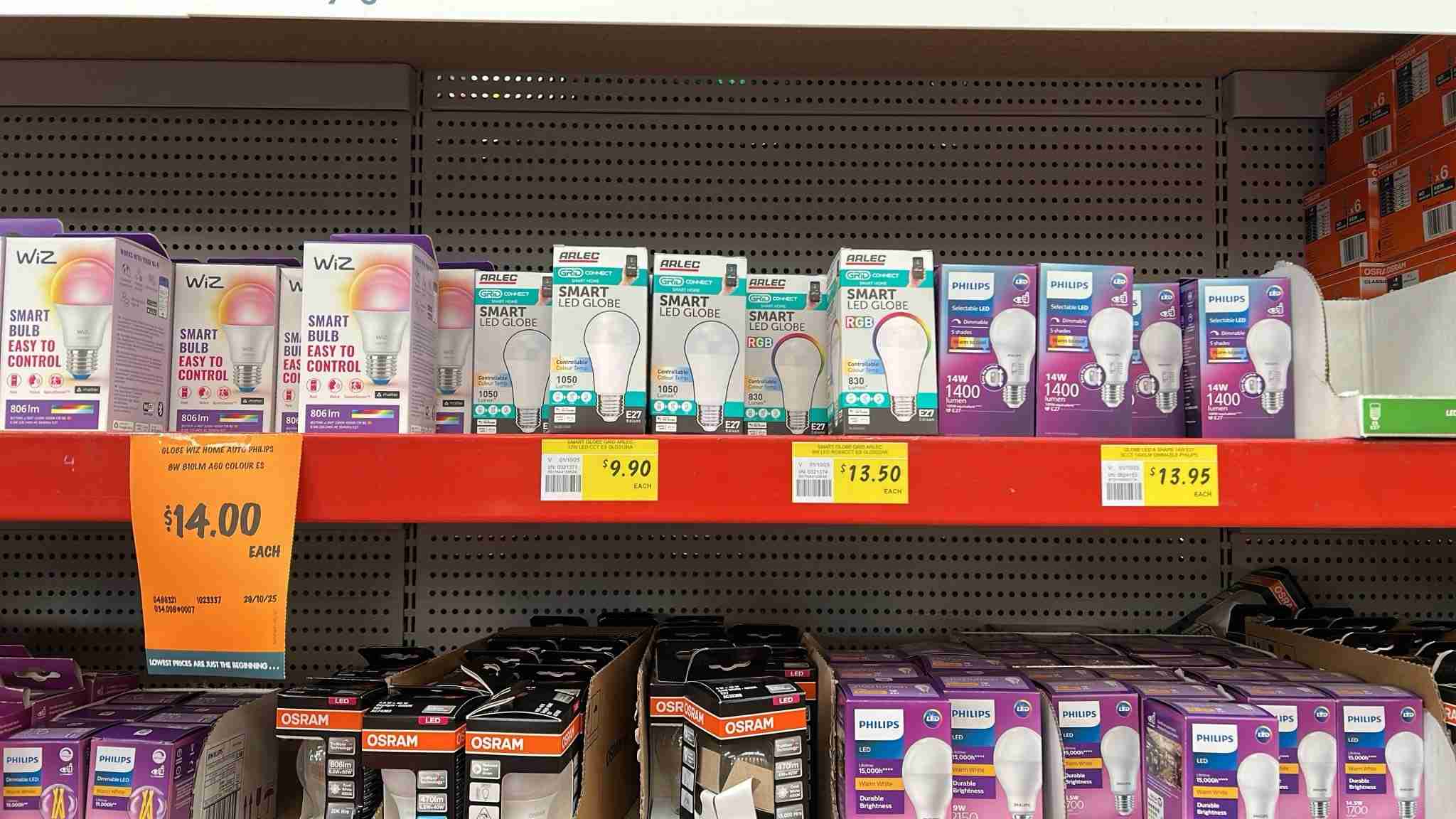
The ARLEC GLD312HA is available from Bunnings Hardware for the astonishingly low price of $AU 9.90 for a WiFi smart bulb. Officially it's known as the "Arlec White Grid Connect Smart E27 LED 1050lm 12W CCT Colour Mode Globe". It's not a color bulb however, with only cool and warm white colors available (CCT). The biggest disadvange of the GLD312HA is that it makes use of the Tuya cloud to relay your mobile phone's commands. Essentially this bulb cannot be operated without an internet connection to the Grid Connect cloud even though local communications may be available to your computers and phones. That's where this piece of work comes in.

The array of manufacturers and the range of products available is staggering. There are literally bays full of various models and types.
What has been done here is to reflash the controlling chip module inside the bulb with software that can interoperate with the house's automation system OpenHAB or HomeAssistant. Crucially, this can now be done without communications leaving the local network. Clearly this has advantages for your privacy and your network's security.
The software used, OpenBeken, makes the bulb compatible with pretty much all popular home automation systems by virtue of its MQTT foundations. Not only that but it also appears pretty much the same as the Tasmota devices with a very similar familiar interface.
Historically Tasmota, the home automation system which is widely used here at ElectricBrain central HQ, was generally the goto software for reflashing these types of devices. However the bulb/switch/device suppliers/manufacturers figured out their business model was being eroded by the "reflasher" community. Their defence was to replace the modules in their devices with a type that is incompatible with the ESP8266 chip. The module chosen is from Beken Corporation which uses an ARM968E-S 32 bit CPU.
Disassembly

While the computer module and related parts operate at the very low and safe DC voltage 3.3 volts and the programmer runs off USB power, the lightbulb itself runs on mains voltage, which in Australia is nominally 230 volts +10%/-6%. This voltage can KILL you. Do not ignore this warning. Do not attempt to operate or otherwise manipulate an open/diffuser-removed bulb. This unit is so cheap, if stuff goes wrong hardware-wise just call it as a fail and throw it in the bin.
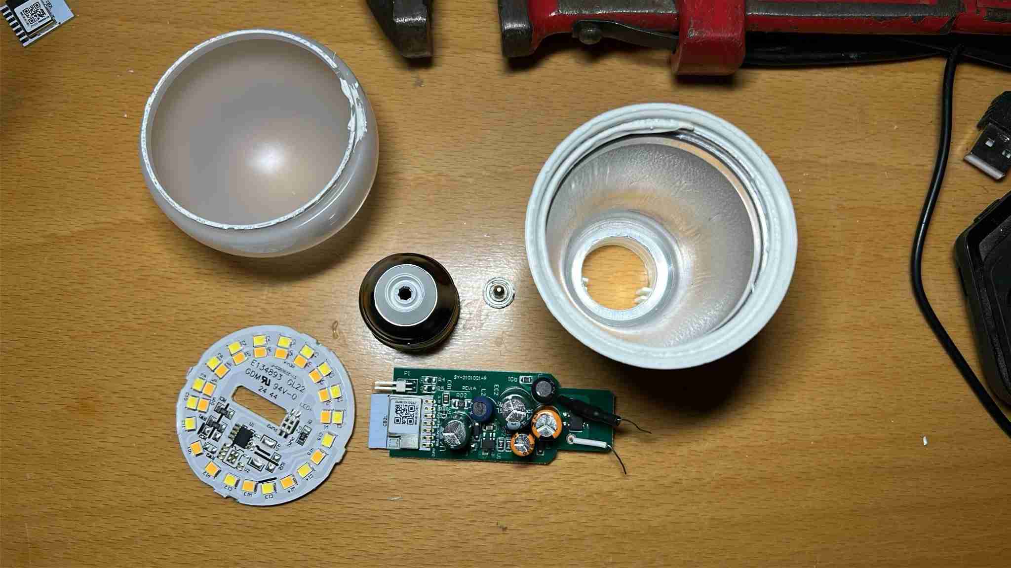
The first step along the road to this transformation and ultimately freedom is disassembly and gaining access to the computer brain inside. Trial and error (dead and smashed bulbs not pictured) has revealed a certain order of operations.

- Remove the T shaped base electrode. Use a Stanley knife blade and a smallish flat screwdriver to pry it loose. This electrode is a firm press fit. Removing it reveals one of the power wires going to the PCB. It's not soldered in and relies on being wedged in to provide electrical contact.
- Firmly grip the bulb diffuser in one hand and the main body in the other. Twist and and pull to remove it. This step is probably the hardest as it does require a certain amount of force. Human hands are great because they won't mark or damage the plastic finish. There is, what appears to be, a silicon gel/goop holding it in.
- Use a pipe wrench to twist off the threaded base. The base is crimped on to the main housing also with some of the silicon goop. Again grab the base in one hand and use the wrench on the metal threaded part with the other. Once removed the other wire is revealed. It is pinched between the main body and the metal threaded base and once again no solder is involved.
- Use a long Philips head screwdriver to poke around the internal PCB up to the LED base plate. Push the plate firmly but gently to dislodge it breaking the silicon seal and it's mechanical fixing properties. Try to do this from various angles to avoid bending the plate. At a certain point in the process you can use a flat head screwdriver to pry the plate out. This part is a delicate operation and it may seperate the connector between the main power supply/CPU module and the LED plate, which is fine as that has to be done in any case.
Module removal
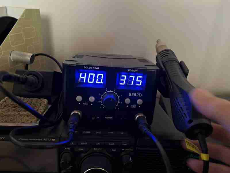
This step requires some special tools. In particular a soldering station equipped with a heat gun.
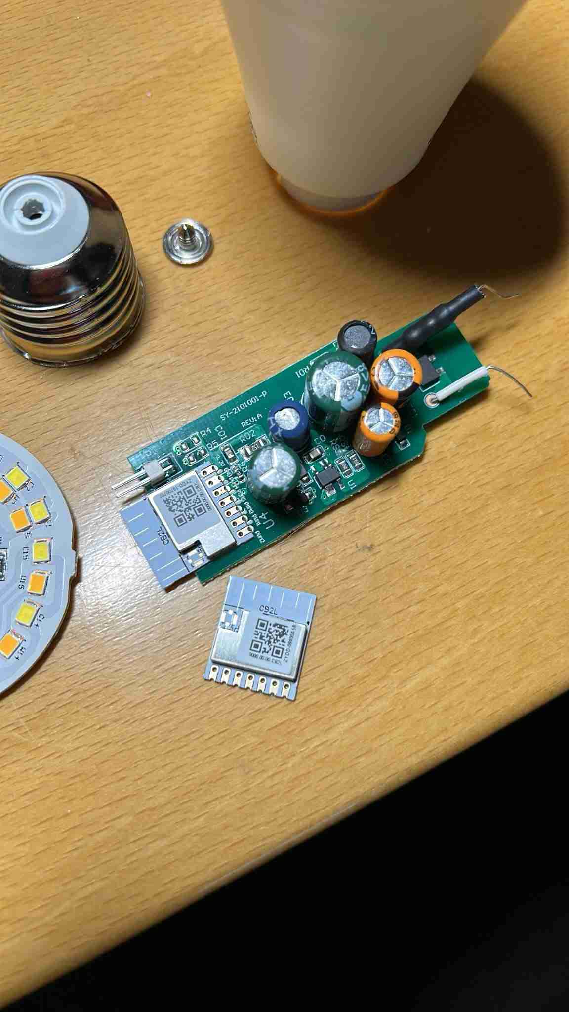
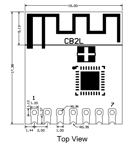
Pick the main PCB up by the WiFi antenna end of the module. Point the heat gun at the 7 pins on the other end of the module until the PCB falls away. There done! It's that simple.
Attaching the programmer to the module
Ideally we would have a jig based programmer ready to go. However the reality here is that the old programmer from the old downlight days has been pressed into service once again.
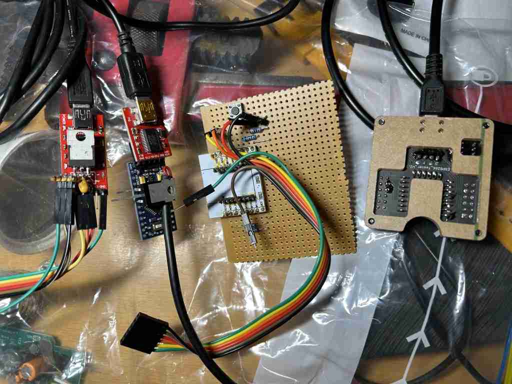
The USB unit used here is shown on the left. These can now be purchased directly on AliExpress/eBay/Amazon with the 3.3v regulator already built-in.
Update: 2026.06.10
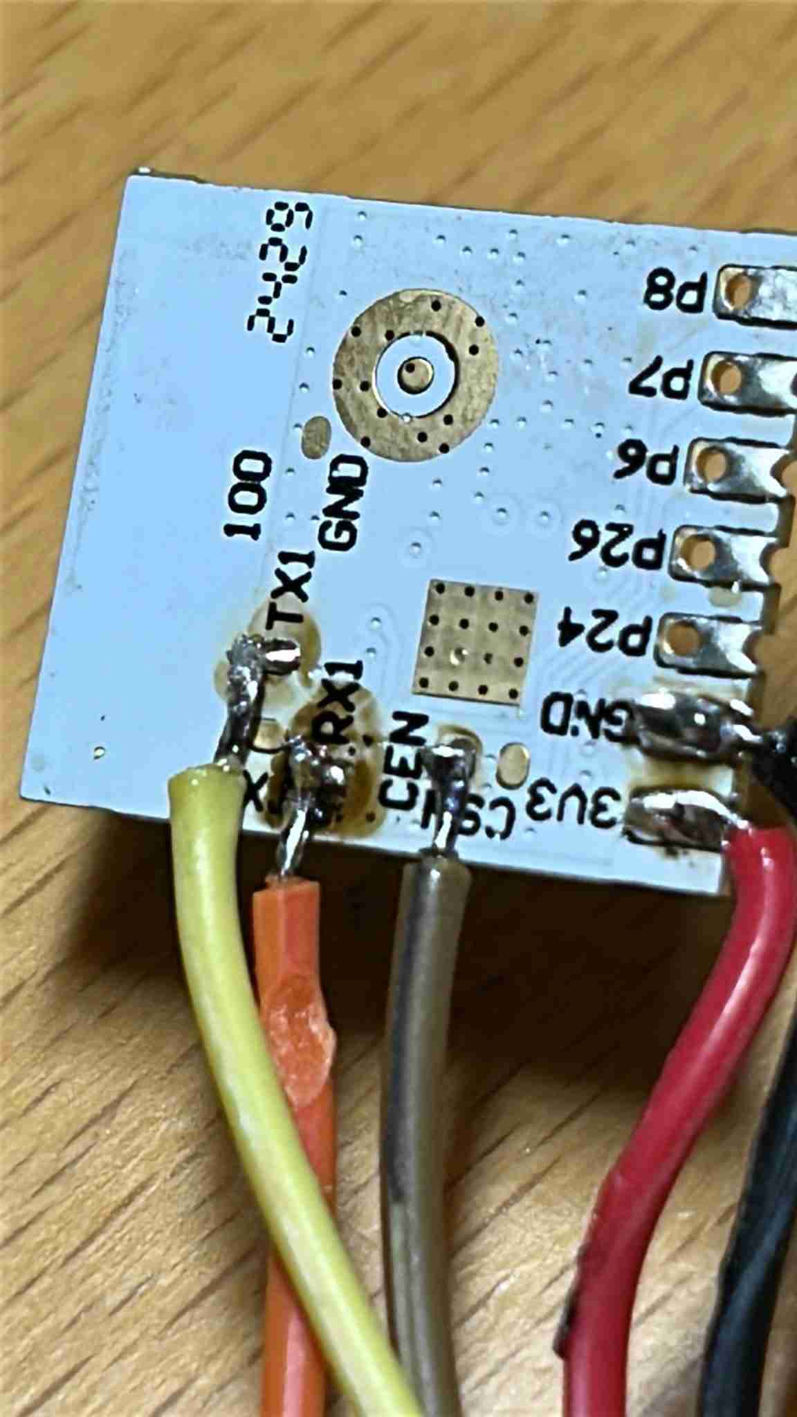
After attempting to burn a series of 5 light bulbs it became clear the the tiny pads shown here, with wires soldered to them, were being ripper off the PCB. The answer is to solder a very flexible filament to the pads as shown below. The filament was taken from a stripped wire and only a single strand is soldered on:
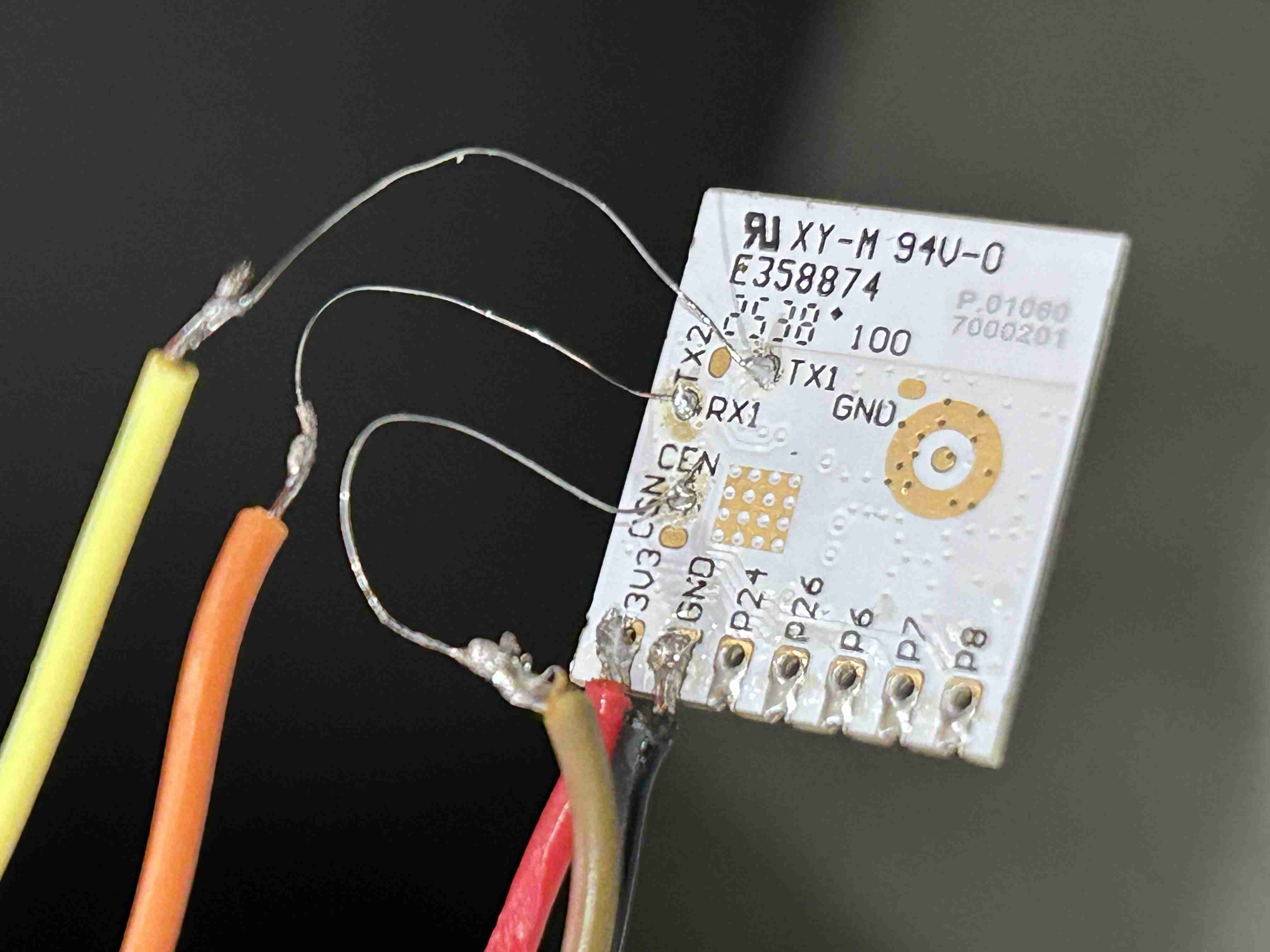
The other end of the programmer wires are attached to module pins
- +3.3v <= +ve regulator output
- GND <= 0v
- CEN <= 0v for booting into programming mode
- TX1 <= rx
- RX1 <= tx
Software - Burn baby Burn
Now the fun part begins.
Initially the wrong software was loaded in to the module. Infact even figuring out how to upload anything into the module was a bit of a challenge. The software used in the end was a package named ltchiptool. Installing it was a challenge all on its own. The main obstacle to successful installation lays with its dependance on wxPython.
The extent to which wxPython even works with KDE (the windowing system of choice here at Electricbrain) is variable to say the least. There were frequent crashes with everything dying back to the commandline with illegal instruction type faults. In the end simply using commandline invocations of ltchiptool seemed the easiest way to go.
ltchiptool flash write kickstart-bk7231n-2025-05-28.uf2
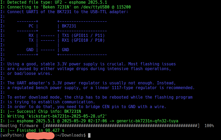
Which worked!!! Proving the basic concept of reflashing this super cheap bulb works!!
However, it's the wrong software. What is needed here at Electricbrain HQ is interoperability with OpenHAB via MQTT.
So an attempt was made to burn OpenBeken into the chip.
ltchiptool flash write OpenBK7231N_1.17.230.uf2
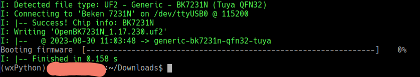
Failure. The indications above show that the burner software immediately aborted with 0% being burned. This is interpreted as meaning that the burner software looked at the partition layout and probably thought something along the lines of: There is already a partition with that name so there's nothing further to do, so I'm stopping now.
Looking into the uf2 images it can be seen that the OpenBK7231N_1.17.120.uf2 file only has one partition in it named download whereas the kickstart-bk7231n-2025-05-28.uf2 file has another partition named app.

The thinking at this point was, since the partitions are already present then all that needs doing it to burn the APP partition with the relevant code. The burner software seems to be able to load .bin files somewhere. As it turned out that somewhere is the APP partition.
ltchiptool flash write OpenBK7231N_QIO_1.18.206.bin

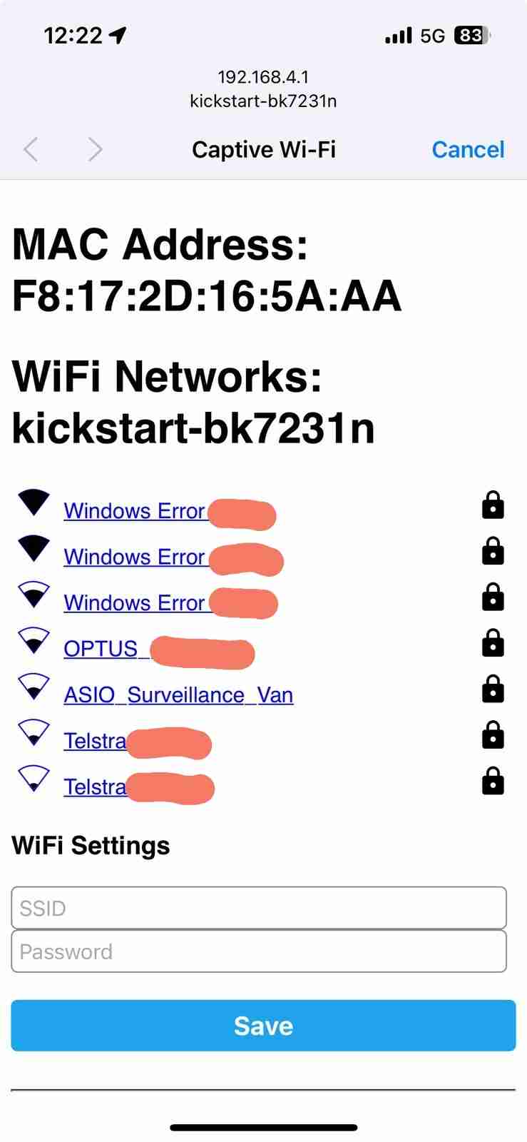
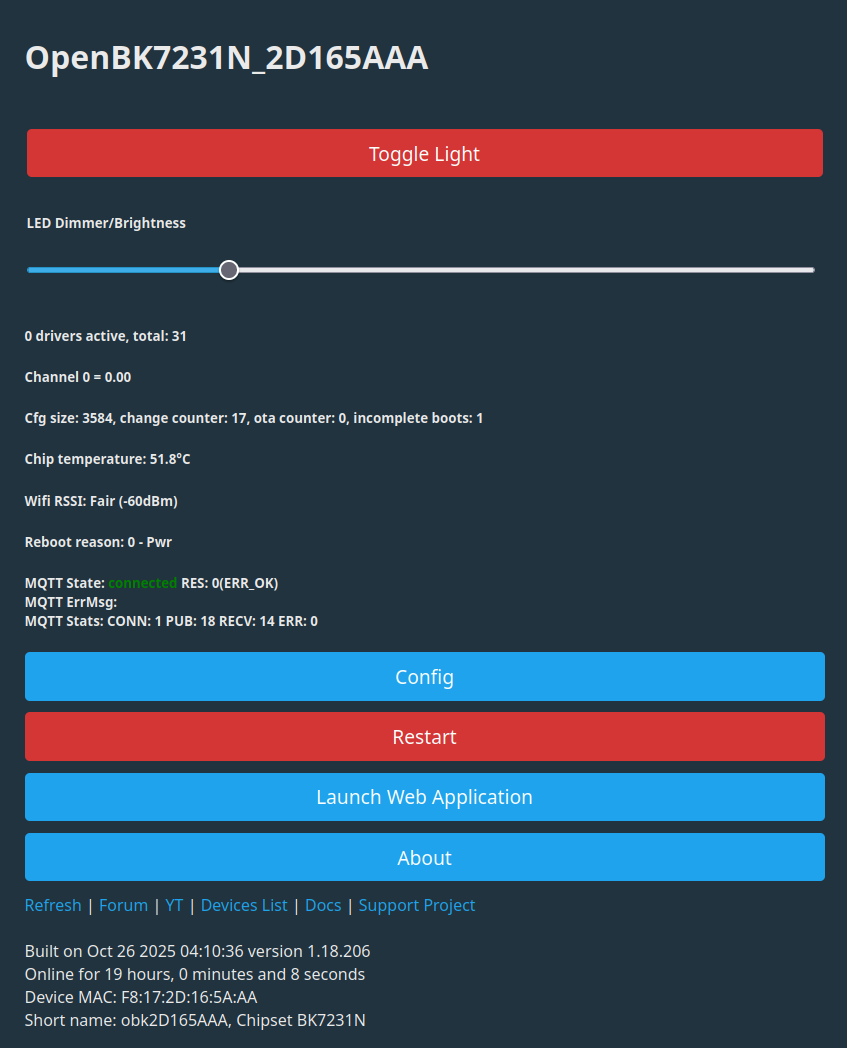
Which resulted in a successful burn. Connecting to its WiFi and the browsing to 192.168.4.1 produced the following.
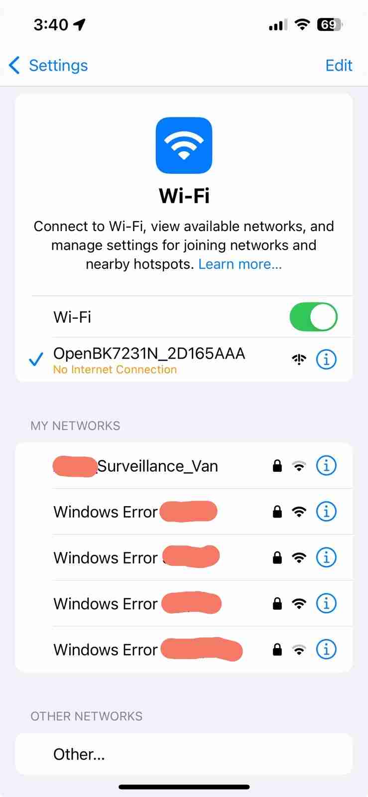
At this point it was a process of attaching to the local network, ensuring that DHCP placed its WiFi interface in the correct LAN segment pretty much as any new device is attached to your network. Finally it's possible to connect from other computers on the network.
At this point the module is ready for resoldering and reassembly.
After reassembly the configuration of the module's pins can be performed. In reality there's no reason it can be done when it's attached to the programmer either.
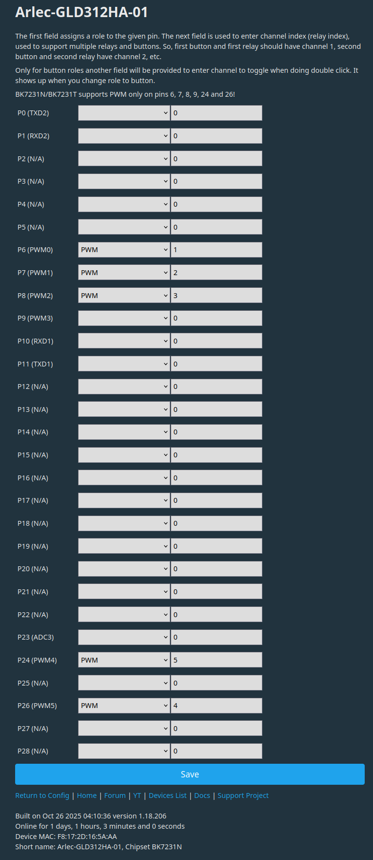
As noted above all the outputs for its big brother - the GLD322HA (the full RGB version) are enabled. The unconnected pins work just fine with nothing connected to them.
It's also a good idea to configure Channel0's level so that the lamp actually comes on at powerup. That caused some concern here after power was applied and nothing appeared to happen.
Reassembly
Reassembly is pretty much the reverse process to disassembly. It was helpful to clean the bottom of the module making it as smooth as possible after removing the attached wires. Then holding the module in place over the main PCB and only soldering a single pad, which in this case was pin 7 labelled as 3v3. This allow fine adjustment of the modules position without unsoldering everything. Once it looks good for position then resolder the remaining pins.
Then feed the main board into the housing with its two wires in an appropriate position. The LED board was plugged in at this point before reattaching the base. This helps to align the main PCB. Next move the base into place ensuring the dark wire feeds into the hole for the lower electrode. Push the base on squeezing the other wire between it and the housing. Finally push the T-shaped disk into the hole jamming the dark wire in.
The final step is to push the diffuser back on. It a pretty firm fit and also serves to position the LED board. At this point it should be possible to test your globe. After testing optionally add some sort of goo around the diffuser base to seal things.
The GLD312HA is now happily talking MQTT with OpenHAB and performing admirably.