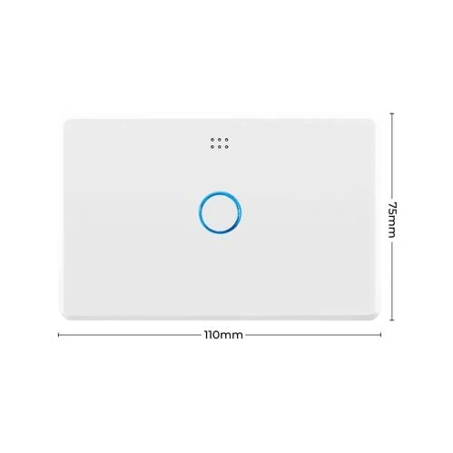
DETA 6911HA Light Switch
Warning
Since this page was written Deta has changed their CPU to a type which is incompatible with Tasmota.
However, this intrepid hacker has successfully overcome this obstacle and purchased the latest revision of the DETA 6911HA complete with its new "unbreakable" CPU from Bunnings here in Australia. Then a brain transplant was performed extracting the incompatible CPU and inserting a Chinese unit (the ESP8266MOD available online via AliExpress) in its place which runs Tasmota perfectly. These actions render the DETA device completely functional.
Complete details will be published here. Needless to say this approach requires hardware hacking skills as well as your software hacking skills.
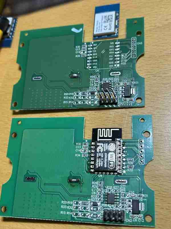
Shown above is the damaged unit (plasterer managed to get water in it) with a practice run of removing the CPU. Below it is the new transplanted CPU module on the latest board from Bunnings Hardware. See brain surgery details
here.
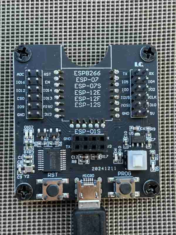
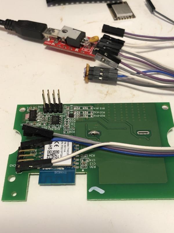
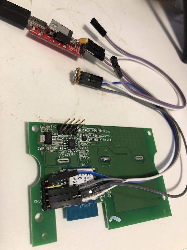
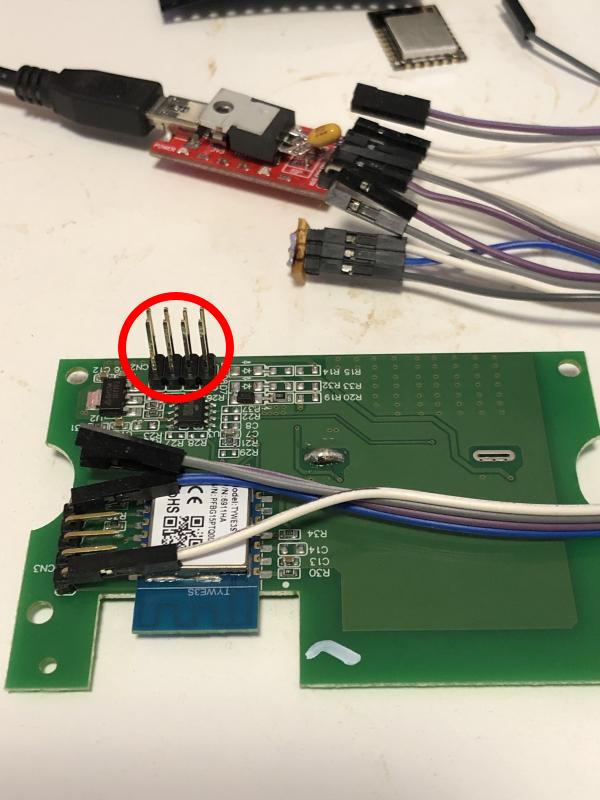
Shown above is the module programming adaptor. All the wires etc in the original article are now replaced by this guy. There are any number of copies/variants of this device, so just pick one and plug the module in to program/flash it. It is recommended by DigiBlur that all programming and testing is performed before soldering the module in.
Note: 22 Jun 2025 - Tasmota version Tasmota 15.0.1 (release-lite)
After considerable to-ing and fro-ing the symptom whereby the software would perform a configuration reset and then reboot was solved. *ONLY* Google AI was able to work out that Tasmota will perform these actions if an input button is pressed "forever". Essentially that translates to leaving an input pin floating not connected to anything (as per the photo above). It follows that the configuration has to be changed/finalized once the module is soldered in place and the pin is either "high" or "low". Everything except the buttons should be defined at this point (i.e. in the jig above).
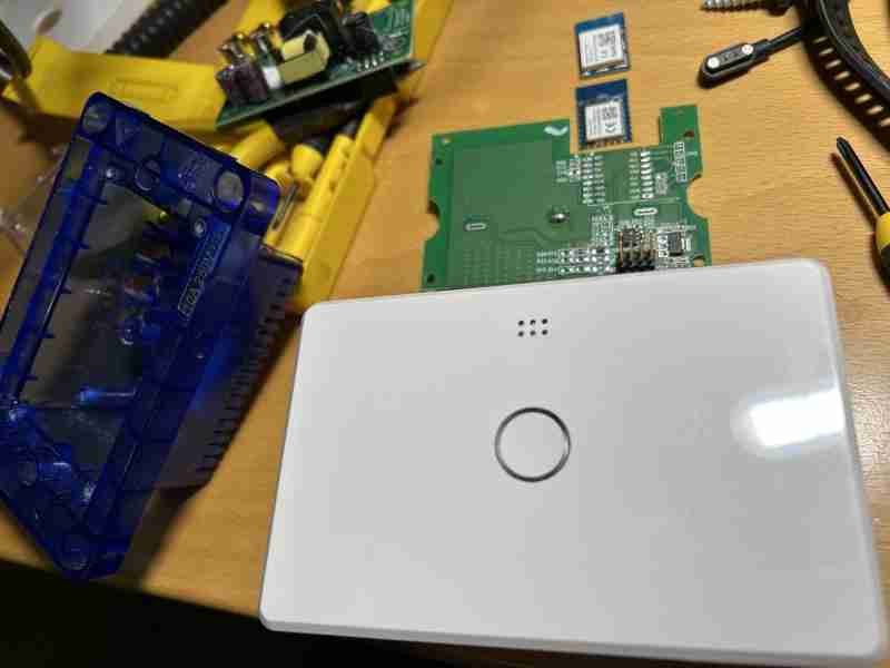
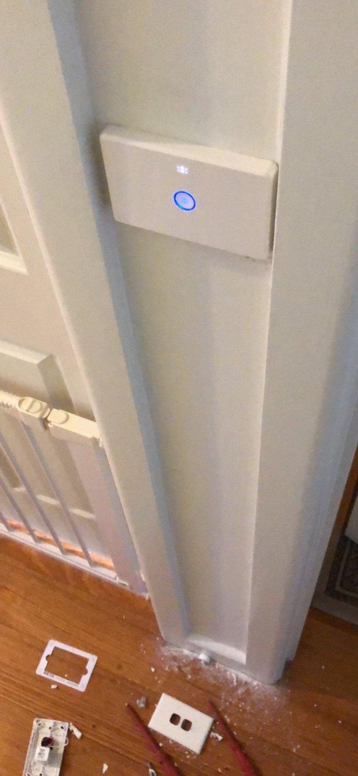
Shown above is the completed 6911HA with the original damaged board above it. Used for soldering practice the two CPUs are shown above that again. One being the 1st generation's TWE3S (damaged) and the latest "unflashable" CB3S.
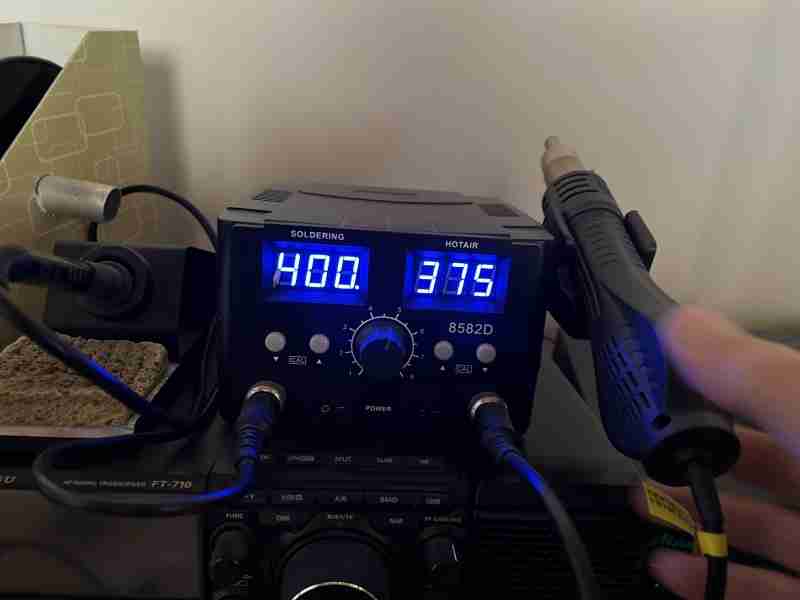
Oh and you'll need one of these guys. Use hot air. The soldering iron for removal will lead to tears. I used the soldering iron to add a tiny bit of solder to each pin once the new module was tacked in to place. Then I ran the hot air over it to tidy up.
Settings
{"NAME":"Deta 1G Switch","GPIO":[0,0,0,0,544,0,0,0,0,224,0,0,64,0],"FLAG":0,"BASE":18}
SetOption settings- Set TZ:
Backlog TimeZone +10; timeDST 1,1,10,1,2,660; timeSTD 1,1,4,1,2,600 - Set Latitude (used by timers to calculate sunrise and sunset)
- Set Longitude
- Discoverabiliy
SetOption19 1 - WiFi - choose strongest on reboot:
SetOption56 On - Send
tele/%topic%/STATEin addition tostat/%topic%/RESULTfor commands:
State,Powerand any command causing a light to be turned on.0= disable (default)1= enable
SetOption59 1 - Auto turn off after 45 minutes
Rule1 ON Power1#state=1 DO RuleTimer1 2700 ENDON ON Rules#Timer=1 DO Power1 Off ENDON
Rule1 1
Tasmotizing
Note on the following linked article:
The header shown in the photo has Vcc (3.3v) on the top pin and Gnd on the bottom pin. The programmer shown is identical to the one used here with the exception that the yellow 6 pin header was removed and the 5v track to the pin cut. An LM3940 3.3v regulator was installed in its place (Note:The 33nf cap and 5.6k resistor on the bottom must be added or the regulator won't run).
https://www.cc27.xyz/2020/04/05/deta-smart-switch-review-tasmota/
The image below shows the flying GPIO0 pin which pokes PIN4 of the module duing powerup. It's a bit hit and miss but a couple of retries sees it work and bring the unit up in programming mode.
Due to the transparent plastic cover literally touching the entire bottom of the board, the header pins had to be removed. The next one might have to be soldered from the top and remain flush on the bottom.
The author of the article above (@cydia2020) also suggests that if you have an unmodified Jaycar programmer then it can be directly attached to the 5v pin on the LED header:
A further reference:
https://blog.mikejmcguire.com/2019/12/09/deta-grid-connect-smart-switch-and-home-assistant/
Installed