Disclaimer
I am not an expert in any of these subjects. In particular I am a newbie to Home Assistant and ESPHome so my configurations could easily be sub-optimal (but they are working for me).
Introduction
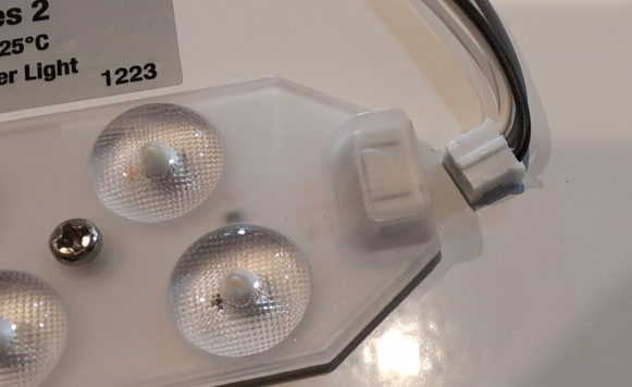
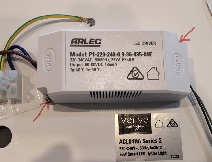
This is a guide to replacing the original (Tuya) firmware in a particular colour temperature LED oyster light available in Bunnings (Australia). The model is sold as Verve Design Smart LED Oyster Light HANA with ACL04HA Series 2.

Options for replacing factory firmware
-
ESPHome via kickstart (CLI)
This is the focus of the guide -
ESPHome using pre-built yaml configuration (CLI)
Skip the kickstart and go straight to a working configuration -
OpenBeken
Go via a pathway somewhat similar to Tasmota Flash CB2L to OpenBeken
About the Microcontroller
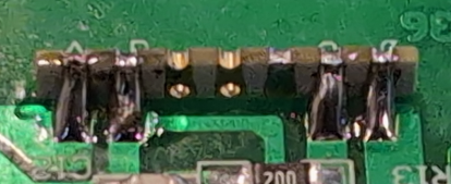
The light contains an LED driver board with a Tuya CB2L module, which in turn is controlled by a Beken BK7231N microcontroller.
IMG_20240823_141436_075.jpg
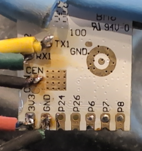
IMG_20240823_141444_262.jpg
Tools
Hardware
- Soldering Iron
- Solder-wick
- Soldering Flux
- Alcohol (IPA, and I don’t mean India Pale Ale)
- USB-Serial adapter w/3.3v output. Most flashing guides recommend a separate power supply but maybe I’ve just been lucky - never had any issue with ESP32, ESP8266 nor CB2L module, including doing OTA firmware upgrades.
Software
- Linux computer with python(3) and an available USB-A port. You can probably do this using Windows but why would you?
- ltchiptool
- ESPHome (within HomeAssistant or ESPHome Standalone (CLI))
- Optional, Windows Only BK7231GUIFlashTool. Couldn’t get this running under bottles nor with dotnet in Linux
Instructions
Disassemble
- After removing the diffuser (by twisting anti-clockwise), remove the blue and brown wires from the connection block
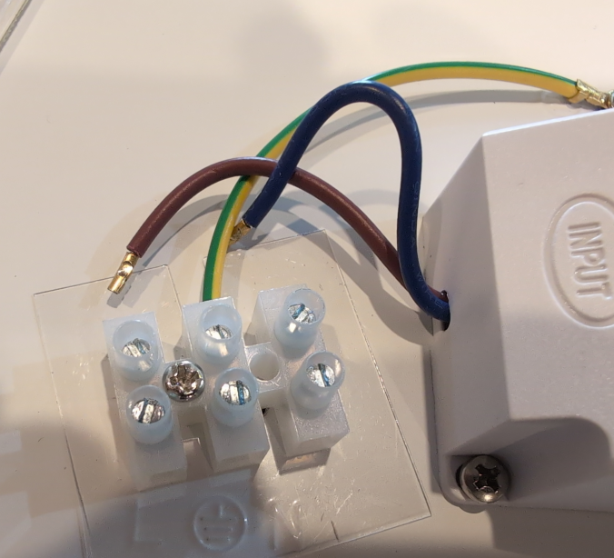
- Unplug the LED Driver unit from the first LED assembly.
- Remove the screws fastening the LED Driver unit from the light base.
- Pop the plastic cover out from the “bottom” of the LED Driver unit and remove the LED Driver
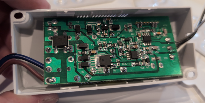
- Desolder the module from the LED driver board.
Solder (or pogopin) the following connections. Select 3.3V output on your USB adapter if necessary (do not apply 5V to the CB2L)
|——————————————|————————————————————————————————————————————|
| CB2L pin/pad | Serial adapter pin                         |
|——————————————|————————————————————————————————————————————|
| TX1          | Rx                                         |
| RX1          | Tx                                         |
| 3V3          | 3.3V                                       |
| GND          | Gnd                                        |
| CEN          | via momentary button to Gnd, or loose wire |
|——————————————|————————————————————————————————————————————|
- Backup the original firmware with
ltchiptool flash read bk7231n [GiveItAFileName].bin - Briefly short CEN to GND to trigger the correct mode. ltchiptool should be running before you reset the chip. The line
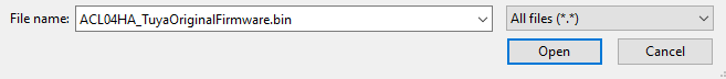
|-- Success! should appear after you reset with the CEN pin/pad. I: Available COM ports: I: |-- ttyUSB0 - CP2102 USB to UART Bridge Controller - CP2102 USB to UART Bridge Controller - Silicon Labs I: | |-- Selecting this port. To override, use -d/--device I: Connecting to 'Beken 7231N' on /dev/ttyUSB0 @ 115200 I: |-- Success! Chip info: BK7231N I: Reading Flash (2 MiB) to 'after_GRID_Connect_paired.bin' [----------------------------------------------------------------] 0% 00:0 [----------------------------------------------------------------] lines omitted... [################################################################] 100% I: |-- - OPTIONAL Using the (Windows only) BK7231GUIFlashTool you can extract the meanings of the pins, by dragging and dropping the output file from step 1 onto the appropriate tab of the tool. Note that the result is NOT accurate for this light. The pins are used for brightness and temperature, and the tool says they are separate cool and warm channels.
Extracted Information BK7231N (10C4/EA60) 0% 00:0 [----------------------------------------------------------------] 1% 00:0 [----------------------------------------------------------------] 1% 00:0 [#---------------------------------------------------------------] 1% 00:0 Finished in 191.537 s File size should be 2097152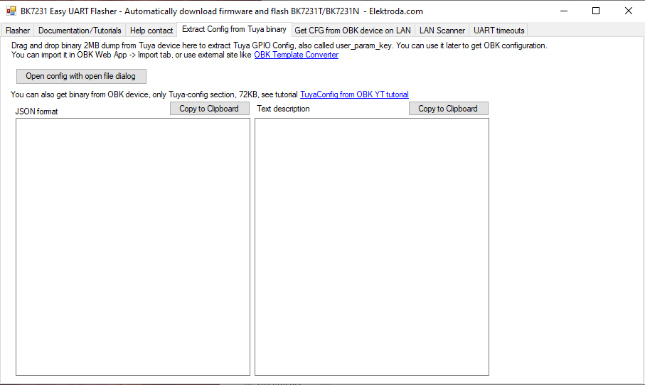
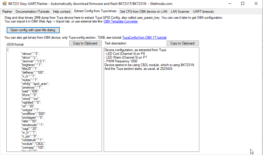
The descriptive text is: - LED Cool (Channel 4) on P8 - LED Warm (Channel 5) on P7 - PWM Frequency 1000 Device seems to be using CB2L module, which is using BK7231N. And the Tuya section starts, as usual, at 2023424 This is the json output: { "rstnum":"3", "rstcor":"c", "Jsonver":"1.0.1", "brightmin":"1", "title20":"1", "deftemp":"100", "c_lv":"1", "mutex":"1", "wfcfg":"spcl_auto", "pmemory":"1", "pairt":"606", "irfunc":"0", "cmod":"cw", "nightled":"0", "wt":"20", "cwtype":"1", "onofftime":"800", "prodagain":"0", "rstbr":"50", "remdmode":"1", "cagt":"20", "w_lv":"1", "c_pin":"8", "notdisturb":"1", "module":"CB2L", "cwmaxp":"100", "dmod":"0", "rgbt":"0", "onoffmode":"0", "brightmax":"100", "w_pin":"7", "wfct":"3", "pwmhz":"1000", "rsttemp":"100", "category":"0502", "defcolor":"c", "defbright":"50", "crc":"32" }
Building ESPHome
ESPHome Standalone (CLI)
Flashing
First Flash (if to ESPHome)
- Download latest release UF2 file from https://github.com/libretiny-eu/esphome-kickstart. At time of writing this is kickstart bk7231n-2023-12-15.uf2
- Wired to ESPHome with ltchiptool
ltchiptool flash write kickstart-pk7231n-[release-date].uf2 - Briefly short CEN to GND to trigger the correct mode. ltchiptool should be running before you reset the chip.
- (this is unnecessary if this step follows the flash read step - the module will already be in the correct mode)
I: Available COM ports:
I: |-- ttyUSB0 - CP2102 USB to UART Bridge Controller - CP2102 USB to UART Bridge Controller - Silicon Labs
I: | |-- Selecting this port. To override, use -d/--device
I: Detected file type: UF2 - esphome 2023.11.6 I: Connecting to 'Beken 7231N' on /dev/ttyUSB0 @ 115200
I: |-- Success! Chip info: BK7231N I: Writing 'kickstart-bk7231n-2023-12-15.uf2'
I: |-- esphome 2023.11.6 @ 2023-12-16 00:08:48 -> generic-bk7231n-qfn32-tuya
Writing (0x011000) [----------------------------------------------------------------] 1%
Writing (0x011000) [...]
Writing (0x011000) [###############################################################-] 98%
Writing (0x011000)
Writing (0x129F0A) [###############################################################-] 99%
Writing (0x129F0A)
I: |-- Finished in 88.907 s
Esphome Config
Issues:
Cannot restore to last known state (set defaults in on_boot section)
Example configuration
ESPHome Configuration Template for ACL04HA Series 2
Instructions
[Notes]
- Replace all instances of redacted with values appropriate to your network
- my devices are on a separate network to my home-assistant and ESPHome servers, necessitating the mqtt and use_address configuration. [ use_address also requires ESPHome to ‘use_ping’]
- I have also enabled the web server to make transitioning to alternate software (OpenBeken) possible.
- You may omit any or all of those items if these conditions don’t apply to your situation.
hana.yaml:

esphome:

  name: hana

  friendly_name: Hana

  on_boot:

    then:

      - light.turn_on:

          id: ACL04HASeries2_1

          brightness: 60%

          color_temperature: 5500K
text_sensor:

  - platform: libretiny

    version:

      name: LibreTiny version
bk72xx:

  board: cb2l
# Enable logging

logger:
# Enable Home Assistant API

api:

  encryption:

    key: "redacted"
# Enable MQTT

mqtt:

  broker: redacted

  username: redacted

  password: redacted
# Enable web interface

web_server:

  port: 80
ota:

  - platform: esphome

    password: "redacted"
wifi:

  ssid: redacted

  password: redacted

  use_address: redacted
  # Enable fallback hotspot (captive portal) in case wifi connection fails

  ap:

    ssid: "Hana Fallback Hotspot"

    password: "redacted"
captive_portal:
# PWM component

output:

  - platform: libretiny_pwm

    pin: PWM1

    frequency: 1000 Hz

    id: pwm_output_1

    inverted: True

  - platform: libretiny_pwm

    pin: PWM2

    frequency: 1000 Hz

    id: pwm_output_2

# using light with the PWM

light:

  - platform: color_temperature

    id: ACL04HASeries2_1

    brightness: pwm_output_2

    color_temperature: pwm_output_1

    cold_white_color_temperature: 6500 K

    warm_white_color_temperature: 3000 K

    name: "Hana Oyster"
(10C4/EA60)
[#---------------------------------------------------------------] 1% Writing (0x011000)
[#---------------------------------------------------------------] 2%
[###############################################################-] 99%
00:00:00W: The current command timeout of 1.0 second(s) is too low for reading 905216 bytes CRC. Increasing to 3 second(s).
[################################################################] 100% Booting firmware
[################################################################] 100%
Reflash from ESPHome to OpenBeken
Through web interface, upload firmware in uf2 format found here
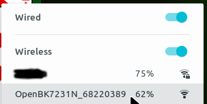
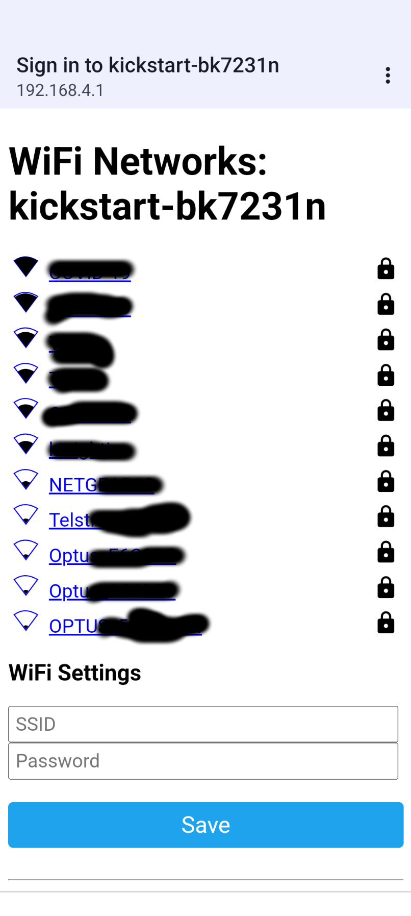
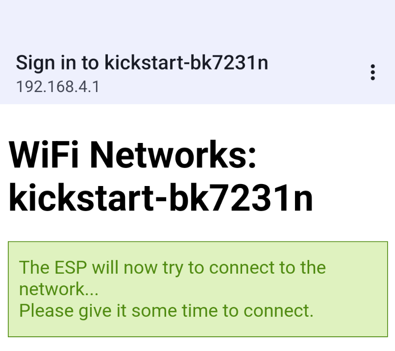
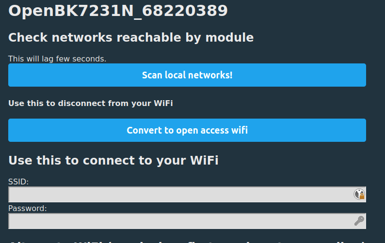
Configure WiFi and Web
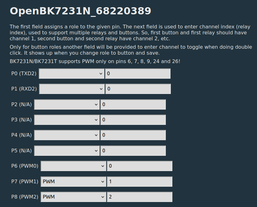
Configure Module
Configure General / Flags
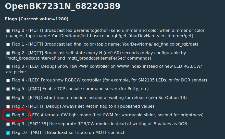
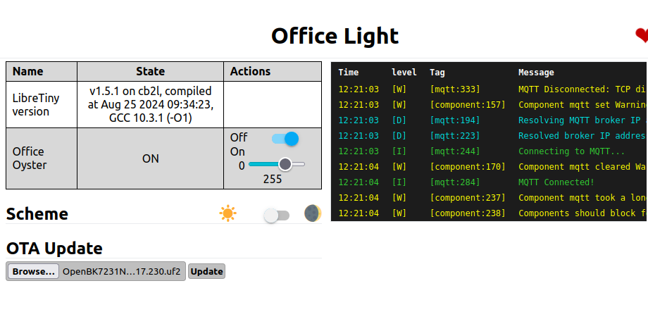
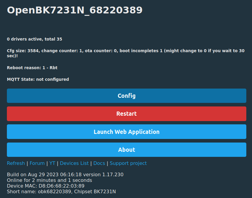
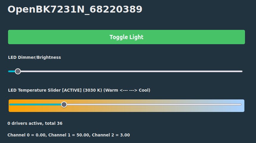
This gets you to a ‘homepage’ that looks like this:
The dimmer works, but the color temperature slider is reversed
I did not persist with OpenBeken from this point, so I have done OTA Restore from OpenBeken to ESPHome. I feel sure that OpenBeken has great potential but for me the effort to understand and integrate it may be a bridge too far.
Reflash from OpenBeken to ESPHome
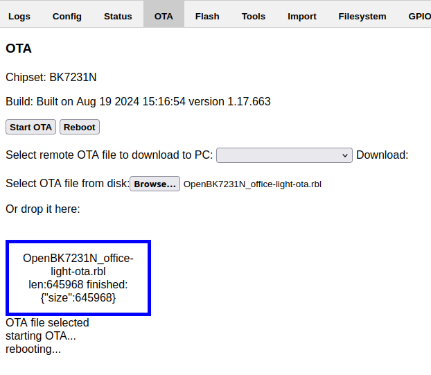
- In the ESPHome web UI, generate a .rbl format file by Edit / Install / Manual and select Beken OTA image.
- Rename the downloaded file so that the filename begins with OpenBK7231N. In my case the filename becomes OpenBK7231N_office-light-ota.rbl (otherwise the openbeken OTA tool will say it's invalid).
- In the OpenBeken Web Application at http://ip.ad.dr.ess/app? (from OpenBeken device page click ‘Launch Web Application’) select the OTA tab, and browse to the downloaded file
- Click ‘Start OTA’
- Generate firmware with ESPHome and manually download it in rbl (Beken OTA) format.
- Rename the file to resemble genuine OpenBeken format (OpenBK7231N_1.17.666.rbl for example) otherwise the openbeken OTA tool will say it’s invalid.
- Browse to [ipaddressofdevice]/app? and select the “OTA” tab.
- Select the renamed file, and Start OTA
References
Getting Started with the ESPHome Command Line
Automatic Tuya pin configuration extraction
BK7231 datasheet, pinout, programming, specification, wiki (BK7231T, BK7231N)
Detailed guide on how to flash the new Tuya Beken Chips with OpenBK7231T
Elektroda YouTube Channel
BK7231GUIFlashTool
LibreTiny
Final Thoughts
I would like to acknowledge the real work that has enabled me to take back control of my own devices. To the developers
of HomeAssistant, ESPHome, OpenBeken and the LibreTiny library go my heartfelt gratitude.
Get your favourite licensed electrician to install the light, and enjoy. Remember, DDIY
There are three unused pins (P24 P26 P6) in this device, opening up the possibility of adding extra sensors, as an exercise for the reader
LicenseACL04HA Series 2 Reflashing Guide by @gerg@hachyderm.io is licensed under CC BY-SA