V2 voltage sensor
Version 2 of the PowerAnalyzer sees the transformer replaced by this cheap mains voltage sensor available from eBay and Amazon.
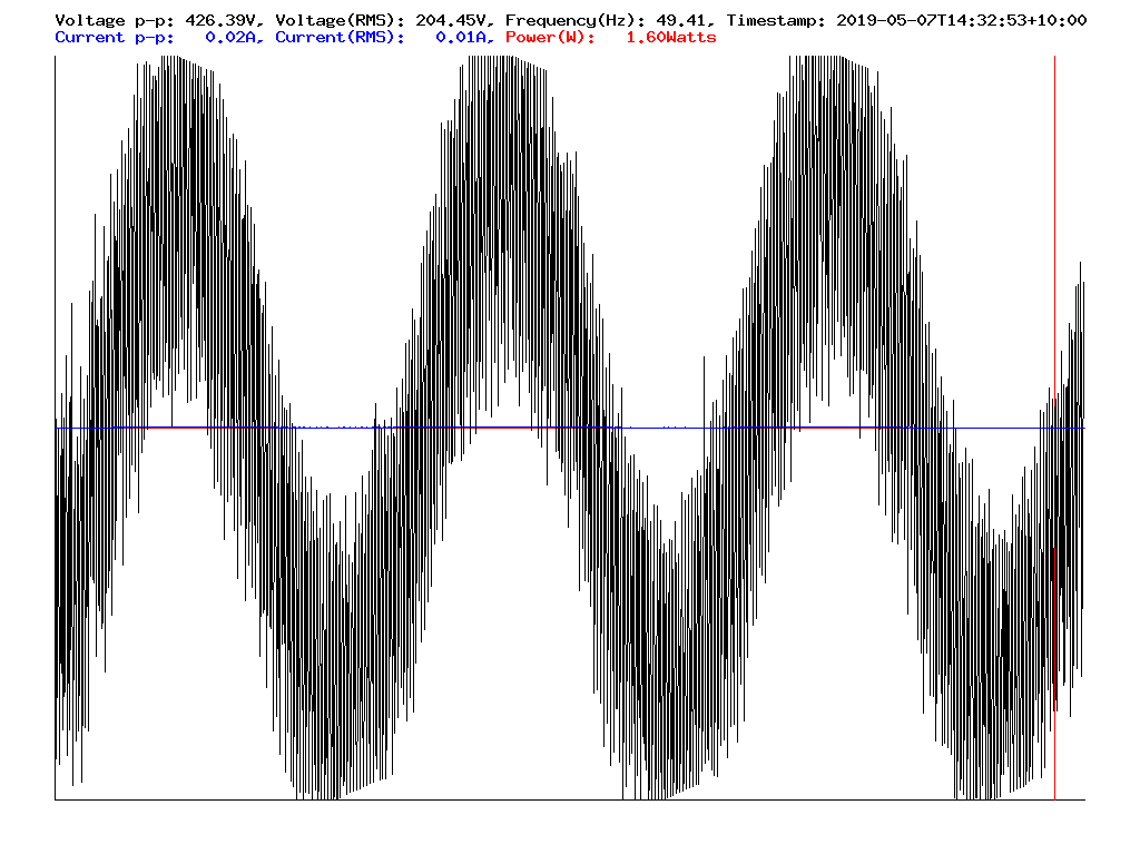
Disappointing performance required some surgery to make it work correctly. See the audio scope output waveforms below.
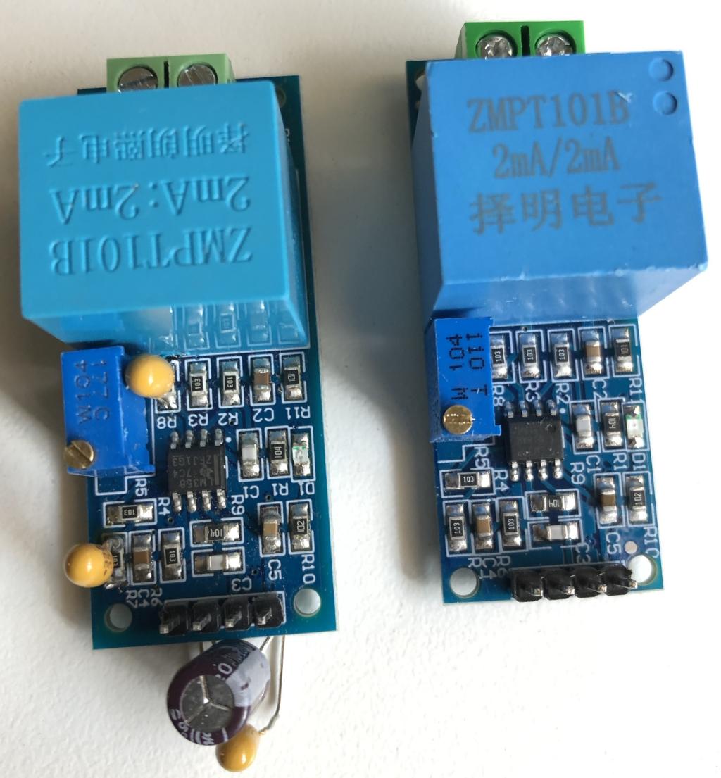
Cheap voltage sensors (that almost work - note surgery to fix it)
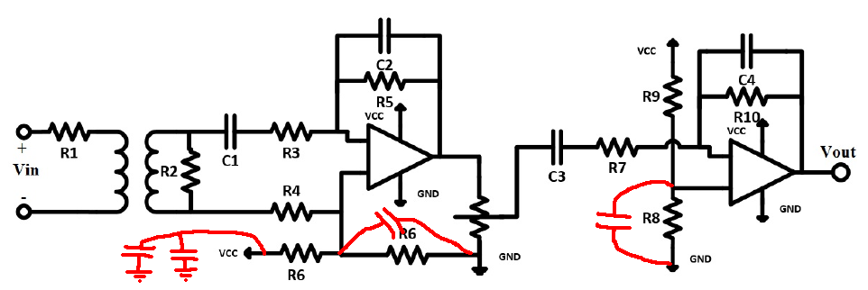
Circuit diagram that approximates the boards in the photo.
The issue which causes the boards to be unusable is mostly the second stage op-amp. The resistive divider couples any power supply ripple directly in to the signal path. The fix was two stage.
- Bypass the power supply with an electro and a tant (220uf [low ESR] + 0.33uf) near the connector.
- Add bypass caps to the resistive dividers. These are 0.33uF tantilums which effectively earth the power supply ripple signal out.
The capacitors must be soldered across R7 and R8 (as marked on the boards - not the circuit diagram).
The power supply used, which has replaced the Pi foundation's recomended unit, comes from Meanwell. It's a high quality unit which appears to have a switching frequency of about 4 kHz as per the scope images.
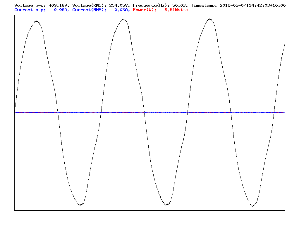
The before and after results are shown below: