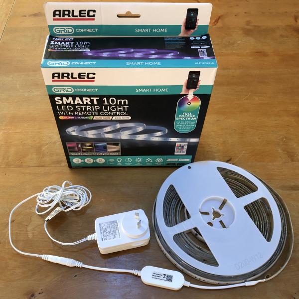
Frankenstein Arlec ALD1056HA
A brain transplant overcomes a problem with a with a spur of the moment purchase of a 10 meter LED strip light. After glancing at the Tasmota Devices Repository it turned out Arlec changed their CPU to be incompatible (which is now noted on the repo page) sometime in mid 2020. This is the story of how the situation was retrieved. (Tasmota configuration template at the bottom).
The problem
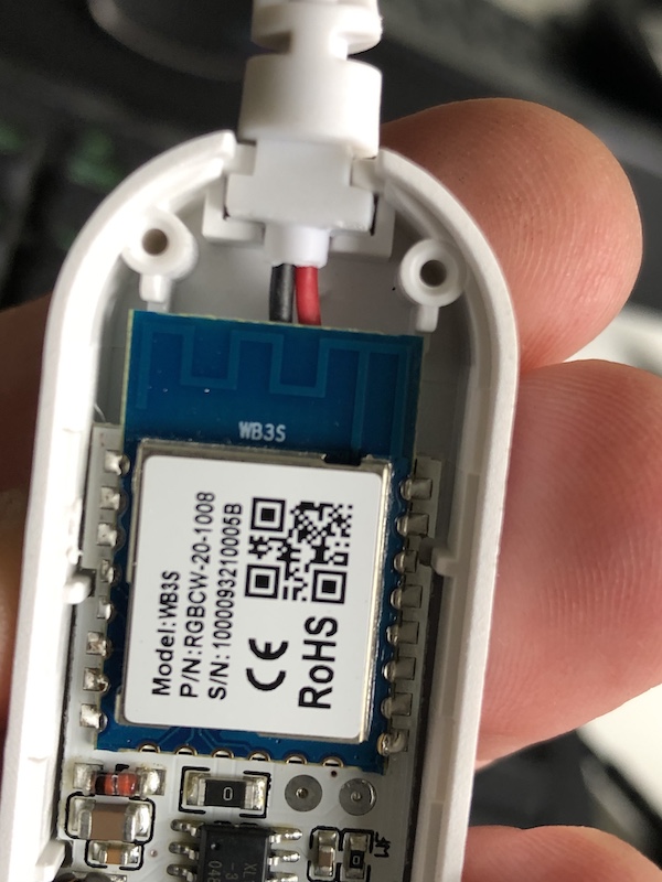
The basis of the issue is that Tuya changed their CPU to be incompatible with Tasmota. At or about mid 2020 Arlec (the local Australian brand name) changed over from ESP-12 series wifi module to the WB3S, which is known to be incompatible with the software.

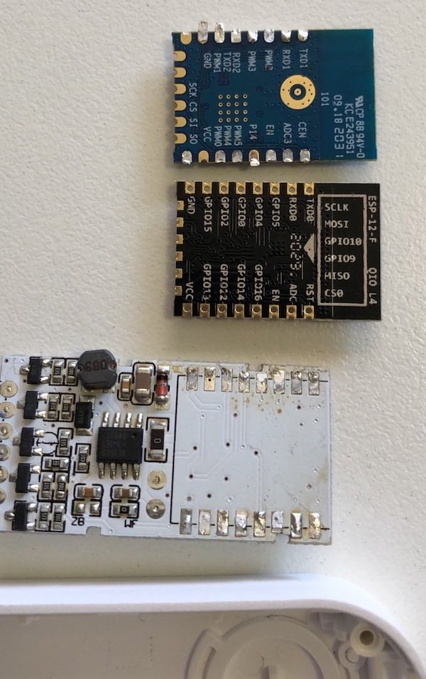
WB3S left - ESP-12F right
Fortunately from a hardware perspective the two modules are largely compatible with the exception of the GPIO15 input. The ESP-12 needs to have this pin tied to ground so that it boots up in the appropriate mode. Most (if not all) WB3S boards leave this pin floating (not connected to anything).
Two attempts at brain surgery
There are various pages dotted about the internet that show successful brain replacements. Very few mention how exactly one removes the original WB3S module with YouTube vidoes generally showing how to remove large soldered on CPU chips.
My first attempt at removal ended in disaster with some of the pads and tracks being ripped up, although the module was removed. Researching the issue it became evident I wasn't the only person to have run in to this stumbling block.
(disaster pic here)
Attempted fix to overcome torn up tracks:
At the time testing showed the module wouldn't boot. This turned out to be due to the GPIO15 issue, and in fact there was nothing wrong except that pin hadn't been grounded.
Having deemed the fix attempt to be a failure a replacement controller was sought. AliExpress had a unit which looked pretty much like the one used on the Jaycar LED strip which successfully Tuya-Converted. The main difference appeared to be it had 5 channels (R,G,B,CW,WW) instead of just the 4 on the Jaycar controller.
Unfortunely when the controller arrived it had the same WB3S module in it....
After thinking about the predicament for a couple of days, it was decided to go for broke, success or bust.
Desoldering
There is indeed a trick to successful desoldering. After watching many many YouTube videos on the topic, it was decided that this is more of an art than a science. The basics are that the solder and hence the whole area needs to be heated to about 200C. Then there's the issue of applying an appropriate amount of force to lift the component.
So the successful strategy used here was (unlike attempt #1) to hold the board in a pair of long-nose pliers by the antenna area on the module. When enough heat is applied the weight of the main board simply causes it to fall away.
Also, unlike the first attempt and indeed the start of the 2nd attempt, the heat gun nozzle size was increased to the 3rd smallest (from the smallest) which upped the heat quite a bit. Being careful to avoid pointing the heat gun at the other components and using a circular motion around the module castle joints for a good 3 minutes or so (your milage might vary a lot here), the main board just fell away to the floor. This is really good because so little force is used that no tracks are lifted.
It's pretty clear that applying these simple learnings to the original controller board would likely have worked in precisely the same way. Alas, the reader can benefit a lot here where I failed.
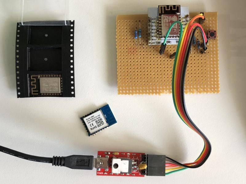
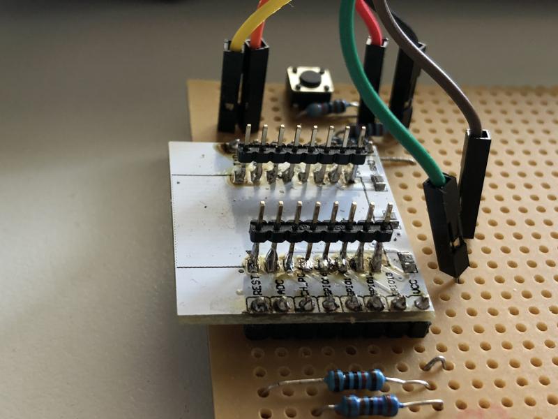
The replacement brain was Tasmotized in a special home made jig (before transplant - shown Tasmotized in pic):
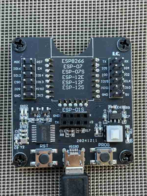
The USB programmer has the 3.3V hack applied where the header once was. That means targets that require 3.3v (which is pretty much everything now days) can be directly connected.
You can now buy any number of devices which do this job on AliExpress, Amazon, etc.
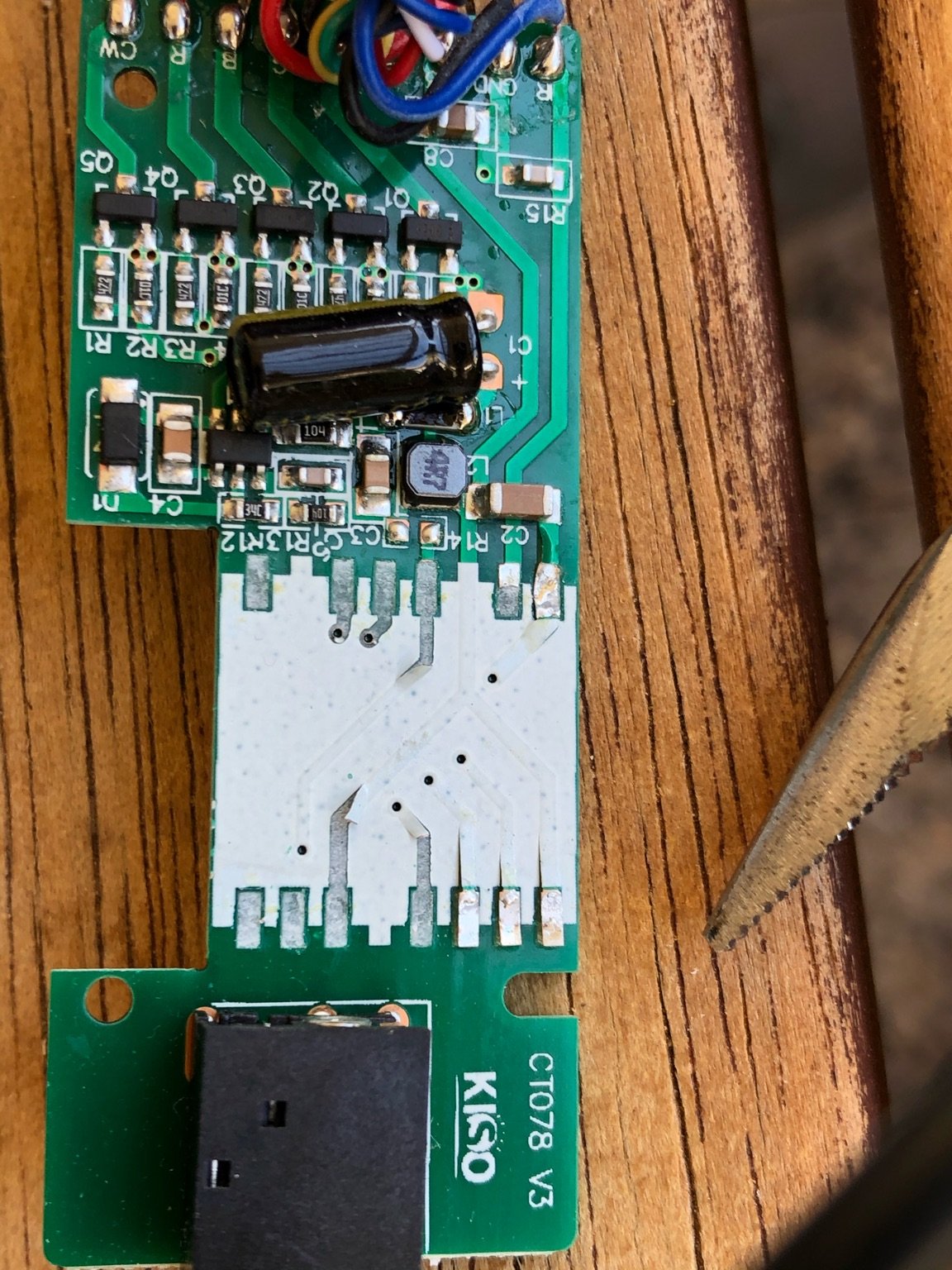
Below shows the 2.0mm pin spacing required for these module. RS-Components to rescue on this one. The industry standard is 0.1 inch spacing or 2.54mm. The breakout board has the headers directly soldered to the pads (don't look too hard but). Then all that is required is to push the ESP-12 on to the pins and Tasmotize away.
The Transplant
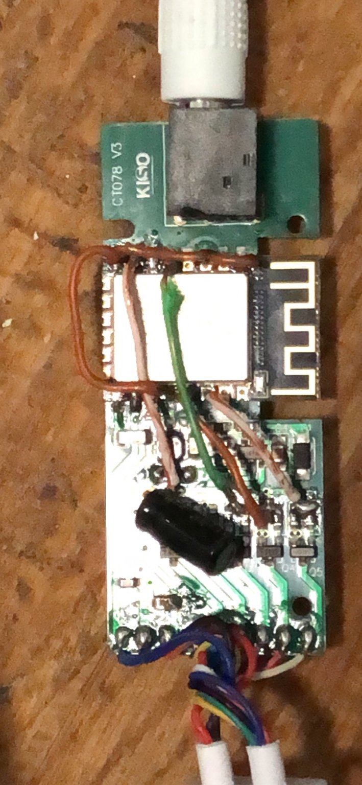
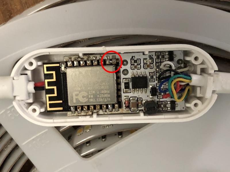
The actual transplant is pretty straight forward. Just place the ESP-12F module and tack it in place on a couple of pins at either end. Then solder each castle pin in place. Finally run the heat gun over the result to produce an original looking job.
The final step was to hack off the original controller's RGBCW wires and reattach them to the new board. They were actually correctly labelled and colored on the LED strip end, but R-G were swapped on the original board. On the new controller no such swapping was required. The points on the new board were nicely labelled and everything went as per the labels.
Gotcha
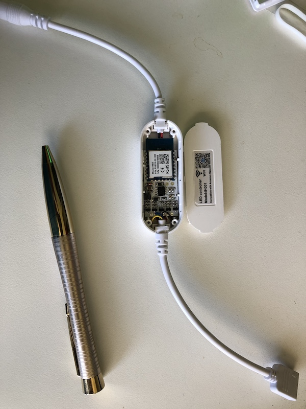
After all that, the second attempt failed to boot just like the first. Debugging with a multimeter revealed GPIO15 was not grounded. This is also noted in some brain transplant web pages too. So as can be seen from the very first photo above, a small link was soldered in place between ground and GPIO15.
Configuration template
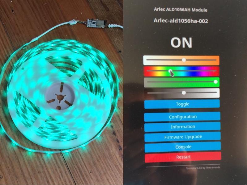
After that, the unit fired up immediately ready for configuration:
{"NAME":"Arlec ALD1056AH","GPIO":[0,0,0,0,416,419,0,0,417,420,418,0,0,0],"FLAG":0,"BASE":18}As can also be seen from the first photo, the IR receiver was unceremoniously attacked with the side-cutters. It's gone to a better place.