Upgrading the OpenEVSE car charger.
By Contributor Dave
This is my story about upgrading the firmware in the OpenEVSE Controller and OpenEVSE Wifi. The Short section is a quick summary of how to do it. The Long is a verbose discussion about the process I followed (including the blooper).
The Short
Quick guide on upgrading the firmware of the controller and wifi modules of the OpenEVSE charger.
OpenEVSE Controller module
The Controller module can be programmed using a USBasp programmer. The source code is cloned using git and compiled and uploaded using platformio.
- Remove Controller module from the enclosure (this may not really be necessary)
- Connect module to programmer and programmer to computer
- Run the following commands to get the source code and upload to the board
git clone https://github.com/OpenEVSE/open_evse.git
cd open_evse
pio run –target upload
Note: I have been made aware of alternate code here. It has alternative installation instructions.
OpenEVSE Wifi module
The WiFi module can be updated over the air or by the serial port. This describes using the serial port and esptool. The serial port of the module is connected to the host computer using a USB to Serial adapter. It is imperative the control signals operate at 3.3V. The adapter I have has 5V power output and 3.3V signal output, ideal for powering the module.
- Disconnect the WiFi module from the Controller
- Connect Gnd, Tx and Rx of the module to Gnd, Rx and Tx of adapter
- Connect Gnd and 5-16V of the module to a suitable power source
- Connect adapter to PC and apply power
- Download openevse_wifi_v1.bin.zip and extract the firmware.bin file
- Install esptool
- Open a command prompt and change to the directory with the extracted firmware.bin file
- Run the following command where COM7 is the port the adapter is on.
esptool.py --port COM7 --baud 921600 --before default_reset --after hard_reset write_flash -z --flash_mode dio --flash_freq 40m --flash_size detect 0x10000 firmware.bin - While the tool is running, press and hold the EN button on the Wifi module. While still holding EN, press and release the BOOT button. Uploading should now begin. EN can be release.
The Long
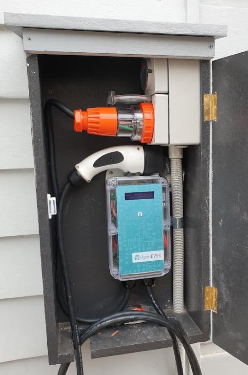
When I bought my wife a Renault Zoe at the Australian “ we are out of here” clearance sale in late 2020, it did not come with any charger. So I ordered an Openevse car charger. I assembled the kit, sourced an Australian 32A plug and installed the unit. A very pleasant experience with a great outcome.
I have recently had a solar system installed. I chose the Maxeon 5 410 watt panels with integrated Enphase IQ7a microinverter. A total of 34 panels, in an east-west layout should be plenty of capacity for a carbon free car and hopefully some left over. Coupled with the Enphase Envoy and a Rainforest Eagle there is enough information available to control the charger.
The Eagle and the Envoy both have a web page that I can scrape for json information. I wrote a script that uses curl, jq, mosquito_pub and mysql to get the web pages and send the results as MQTT messages, and also log to the database.
OpenEVSE also uses MQTT. If enabled, it can be configured to get the power and voltage of the power network. Under the Services tab on the OpenEVSE web page, which can be accessed either though the WiFi hotspot or the local network if OpenEVSE has been configured.
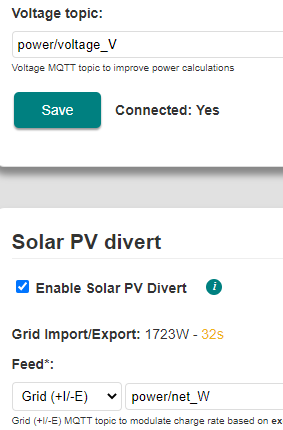
As you can see, I have set up mine to use the topics mentioned above. The only thing I wasn’t sure about was the units for Feed, should it be Watts or kiloWatts. I used watts and as you can see in the picture above, it is displaying a reasonable value for Grid Import/Export.
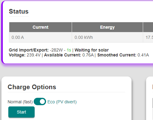
To see the voltage, select the OpenEVSE tab in the browser, and enable Eco (PV Divert) in the Charge Options section and also turn on Advanced in the Display section. The MQTT power and voltage data can now been seen in the Status section. Note the very small feed in of 282W and consequently the very small available current.
The OpenEVSE also publishes data to MQTT. Using MQTT Explorer, it is possible watch the messages that are being exchanged on MQTT.
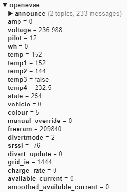
The voltage and grid_ie values published by the charger are the same as those that OpenEVSE is reading from MQTT.
With everything set up, it was time to test. I plugged the car in and watched. It all seemed to be working but suddenly things went crazy. The charge current was oscillating up and down. It didn’t make any sense. Then I noticed the available charge current was in the thousands of amps. What’s going on?
I looked through the MQTT Explorer data and extracted the following published messages.
| Source | Time | Volts |
|---|---|---|
| envoy | 13:31:05 | 252.004 |
| openevse | 13:31:39 | 252.004 |
| openevse | 13:32:05 | 252.004 |
| envoy | 13:32:05 | 249.457 |
| openevse | 13:32:09 | 249.457 |
| openevse | 13:32:39 | 8.314 |
| openevse | 13:33:05 | 8.314 |
| envoy | 13:33:05 | 251.098 |
| openevse | 13:33:09 | 251.098 |
| envoy | 13:35:05 | 248.612 |
I have highlighted the weird results, where the voltage is 8 instead of 250 or there abouts. This explains the excessively high available current readings mentioned above This quickly pushes the calculated filtered current up and takes forever to come back down.
So that is how I ended up here, needing to upgrade the software to try and eliminate the problem.
The OpenEVSE charger contains 3 modules. I will call them the Display, Controller and Wifi modules. The web interface on the WiFi module provides the ability to upgrade itself by uploading a new binary code image. I was running version 3.3.1 and a search for “OpenEVSE firmware” got me to this repository. Version 4 is available.
The first line of the readme.md is
NOTE: Breaking change! This release reccomends a minimum of 7.1.3 of the OpenEVSE
firmware, features including Solar Divert and push button menus may not behave as
expected on older firmware.
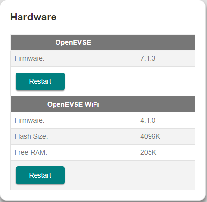
To get the current Controller module version, I power cycled the charger to read the current version of 5.0.1 from the LCD. I later worked out, selecting Display – Advanced, the OpenEVSE and OpenEVSE WiFi versions are both displayed in the Hardware section.
Programming the Controller
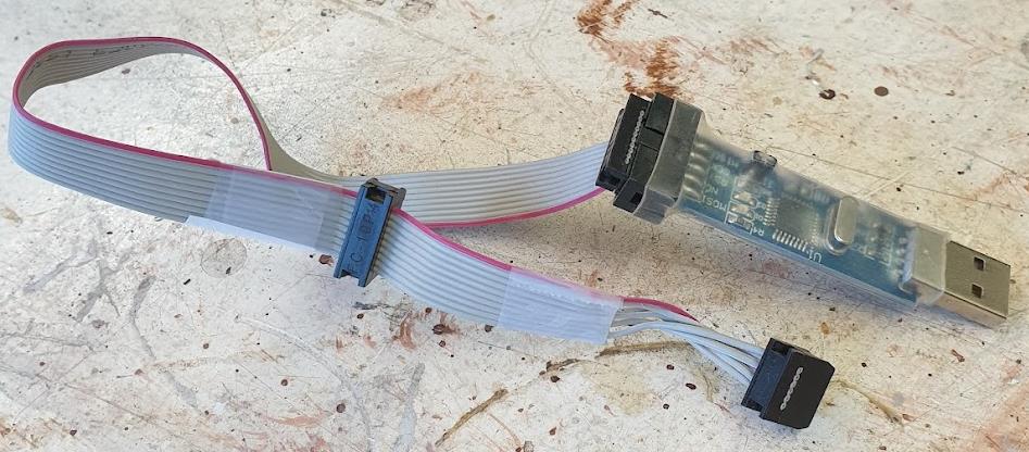
This means a firmware upgrade of the OpenEVSE Controller is required. It uses and ATMega328P processor and cannot be upgraded over the air, nor by USB, or serial but by using a programmer. I knew I probably had one somewhere, from the early days of playing with drones. A rummage around found a USB stick thing with a 10 pin and a 6 pin connector hanging off it. I think this is a USBasp programmer.
Next thing was to get access to the connector on the Controller module. I removed the charger from the wall, took off the cover and though considered whether to program the board in place or disconnect everything. To be cautious and safe, I chose the disconnect everything and remove the module. This way I know nothing will be loading the pins on the processor.
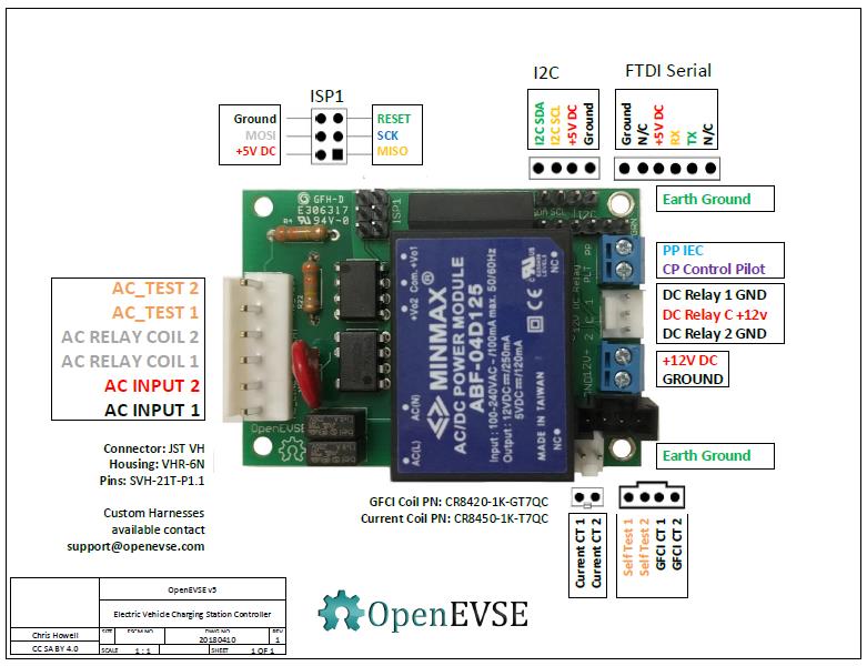
ISP1 is where to connect the programmer. The board itself doesn’t provide much information about the pinout of the ISP1 connector, but the image above helps. The connector is non polarized so it is very possible to connect the programmer incorrectly, possibly doing irreversible damage. To be absolutely sure, I first traced out the wires on the programmer, using the silk screen legend on the programmer as a guide.
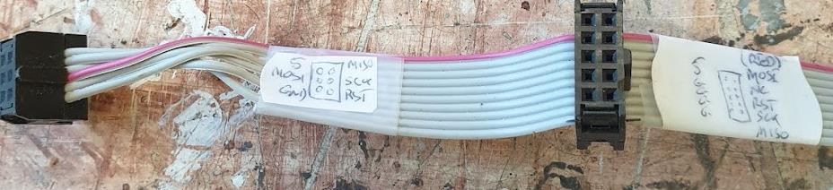
The cable is now labelled, and I can confirm the pins match the ISP1 connector on the Controller module, as long as the wire extends to the right!
Now I need some code to upload. Searching around a bit, I found this repository. This is the source code, not an image, and has an .ino file which is unique to Arduino. I also noticed a platformio.ini file in the list. I thought maybe that would be a better to use platformio since I have been using it a lot in recent times.
I am using Windows, so these comments relate to my experience only, but should also apply for other OS’s.
The first thing is to get a copy of the code. You could download directly from github or clone it using git. I have installed git and used that to clone the repository. On github, there is a button which gives you download options
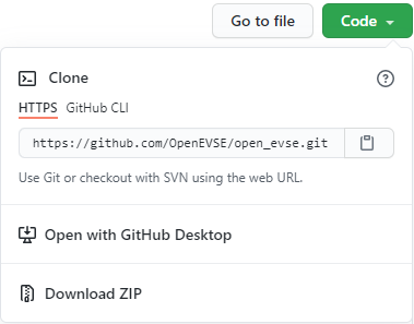
The clipboard image is an easy way to copy the URL for the clone.
From a git bash window I entered
git clone https://github.com/OpenEVSE/open_evse.git
Then change into the new directory open_evse
cd open_evse
I have platformio already installed, so I ran the compiler
pio run
After a few seconds, the required resources had been downloaded and the code compiled without error. Once the module is connected to the computer using the USBasp programmer, it should be possible to type
pio run –target upload
but I didn’t go that path. I instead decided to use Visual Studio Code. To set up the platformio project to use Visual Studio Code (with the platformio extension installed), I entered the following command.
pio project init --ide vscode
Then to launch Visual Studio Code, enter
code .
Visual Studio Code loaded up as did all the source code. From here, we I could compile and upload using a GUI.
At the bottom of the window, there is a tick which is the build button. Press that and the code should build. It didn’t take long as I had already compiled the code earlier.

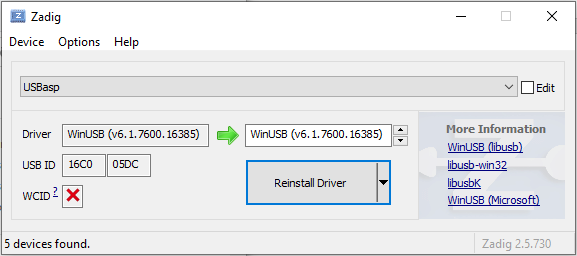
The next step is to connect the USBasp programmer to the computer. I remembered from last time I used it, there were special drivers that need to be installed. A search found this instructable which directed me to download the ZaDig application. I ran that app and installed the WinUSB driver for the USBasp device.
I removed the USBasp for the computer, connected the cable into the ISP1 connector, triple checking that everything was the correct, then plugged it back into the computer. In Visual Studio Code, I then clicked the right arrow ‘upload’ button build button mentioned earlier.

Bingo! It worked, code uploaded.
I reassembled the charger, plugged it in and all seemed to be working fine. The only difference I note is when the power is first switched on, the contactor operates for a few hundred milliseconds.
Programming the WiFi
The next step is to upgrade the wifi firmware. This is when I should have taken a break. It was nearly dinner time, I’d been working on this for hours and I was keen to get it finished. Bad move. I ended up bricking the WiFi module. Now I was really hangry. I had uploaded the wrong firmware.bin file. It is now tomorrow’s problem.
I have not had much exposure to the ESP32. I know it is a fantastic chip. I have a Dev Kit C which I have played with but that’s about it. That board has a USB connector, and Arduino just knows how to upload code, unlike myself. The Wifi module does not have a usb connector so I searched a bit on how to program the OpenEVSE Wifi V1 board with out any luck. This article discusses the topic of programming via the web interface, over the air and by a USB serial programmer. As the module is bricked, the only method that is going to work for me is the serial adapter, but the detail on exactly how to do that is missing. The article recommends this adapter, but I already have a USB to Serial adapter which I will try and use. It also says the programming tool esptool.py is required. The article does have the all-important commands that I need once I get the computer and the Wifi module talking to each other.
The extract below captures them.
If flashing a new ESP32, flashing bootloader and partitions file is required:
esptool.py --baud 921600 --before default_reset --after hard_reset write_flash -z
--flash_mode dio --flash_freq 40m --flash_size detect 0x1000 bootloader.bin 0x8000
partitions.bin 0x10000 firmware.bin
Then successive uploads can just upload the firmware
esptool.py --baud 921600 --before default_reset --after hard_reset write_flash -z
--flash_mode dio --flash_freq 40m --flash_size detect 0x10000 firmware.bin
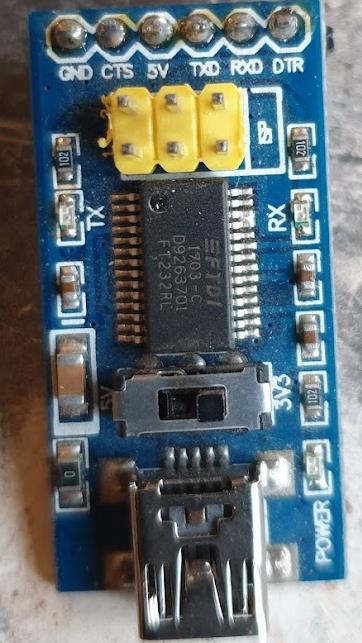
What I need to do now is work out how to connect the adapter to the module. The USB to Serial adapter has a header on it with the pins GND, CTS, 5V, TXD, RXD and DTR.
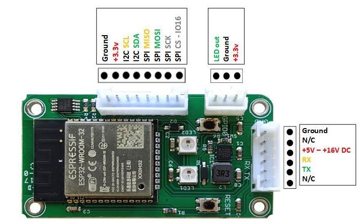
The Wifi module connector has a connector with a similar pinout, GND, NC, 5-15V, RX, TX, NC. If the connectors matched, I could plug them into each other and the power and tx/rx pins would align correctly.
Is is important to note is the voltages. The ESP32 operates at 3.3 volts. USB ports operate at 5 volts. The adapter I have has a 3.3 and 5 volt switch. This could end in tears and smoke if I get the voltages wrong.
The connector on the adapter has one pin labelled 5V. My first question is whether the 3.3/5 switch changes the 5V pin? A quick measure with the multi meter says not. 5V is 5V regardless of switch position. Checking the signal pins shows that only they change. With switch in the 3.3V position, the Wifi module can be safely connected to the Serial adapter as it power input is 5-16 volts.
There must be more to it though. Surely more signals are needed to enable programming. How does Arduino get the ESP32 DevKitC into programming mode?
The DevKitC board includes the USB to Serial module on board. Checking the circuit diagram shows the TX and RX connection as expected and also this additional connection.
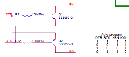
Further reading explains that the EN and IO0 pin are special during reset (along with other pins) and are used to enter programming mode. Reading about esptool here can be directly connected to RTS and IO0 directly connected to DTR. The above circuit protects both signals being low at the same time as same which some serial monitors will do. Further investigation shows EN is the enable on the ESP32 voltage regulator. Grounding this pin turns off the regulator and consequently the power to the ESP32. The IO0 pin is used to get into programming mode. The ESP32 reads a few IO pins when coming out of reset, and IO0 is the one that controls programming mode. I’m a little confused about this. The sequence needs to be IO0 low, EN low then EN high. The above circuit does not low both EN and IO0 to be low at the same time. After a bit more research, I found this bit of the circuit is important.
Apparently, some clones omit this, making it impossible to get into programming mode. (I’m not sure why the resistor is required, the ESP32 has a 45k pullup resistor already).
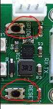
The answer is EN and IO0 need to be controlled for programming. Neither of these signals appear on any connector of the Wifi module, but it does have two buttons labelled RESET and GPIO0. I think this is the answer I am looking for. It is a manual operation to enable programming. In hindsight, it might have been easier if the Wifi module had EN and IO0 on the unused pins on the TXRX connector. RTS and DTR could have then been used by esptool to enable programming.
So now I am ready to trot. Just need to connect the two together. It turns out, the connectors on the Wifi module are the same as the balance connectors on LiPo batteries. I just happened to have a spare 6 pin cable which was great. I used that to make a cable to connect the USB to Serial adapter to the WiFi module and start programming. The color code of the wires didn’t match the OpenEVSE cable, so I popped out the wires out of the connector and put 4 back in using the same colour sequence as the OpenEVSE supplied cable. I then spliced on a wire with a pin on it to insert into the adapter.
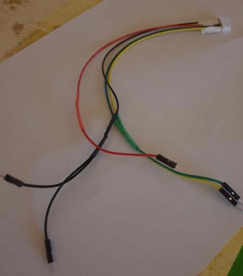
This shows the Wifi module and header on the USB to serial adapter connected together.
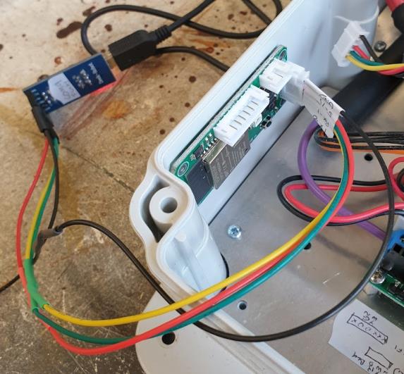
You may notice two black (GND) pins. I did this for two reasons. First, if the USB to Serial adapter did not provide enough power, I could disconnect the +5V wire and connect an alternate power source. Secondly, it gave me somewhere to put the CRO earth clip if the worst case eventuated.
This link has the downloadable firmware required. This is where I made my huge mistake earlier.
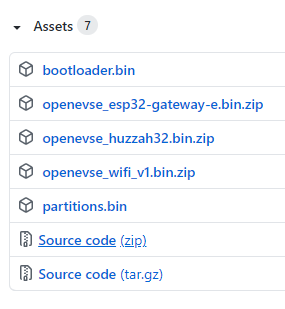
In my rush, I clicked the link with esp32 in it. Don’t you do it. It’s wrong.
Click openevse_wifi_v1.bin.zip and download that. Extract the file (firmware.bin) to a convenient directory.
At the command prompt (I used windows command), change into the directory of the firmware.bin file and enter the upload command from earlier.
If you haven’t already, download the esptool as mentioned above. When I tried to install it, I needed to upgrade Python as well. Ultimately, I opened Add/Remove programs and found I had two versions of python installed. I uninstalled them both and did a clean install of the latest python. I was then able to install esptool as per their instructions.
pip install esptool
Also make sure the USB to Serial adapter is recognised by windows. Drivers may need to be installed to get it to work.
Now is the time to upload the firmware. Using the command mentioned above, start the upload.
esptool.py --baud 921600 --before default_reset --after hard_reset write_flash -z
--flash_mode dio --flash_freq 40m --flash_size detect 0x10000 firmware.bin
The tool will now try and connect to the ESP32. While it is trying to connect, hold down the GIO0 button and press and release the RESET button.
Unfortunately, this failed. It was using the wrong com port. From Windows Device Manager, I found the Serial port that the USB to Serial adapter is using and added - - port COM7 to the command.
This time I had success. Holding the GPIO button while clicking the RESET button is not that easy, so I used a small screwdriver to hold the GPIO button.
At this point I expected success, but not to be. Even though the Wifi module is not connected to the OpenEVSE module, I should still be able to connect to the access point. The Openevse Wifi hotspot would appear in my available wifi locations on my phone but any connection made would drop out again.
I started up putty and connected to COM7 at 115200 baud. The Wifi module was rebooting regularly. What now? Maybe the other bits of flash need to be updated as well. I also downloaded bootloader.bin and partition.bin from the same webpage as the firmware, and ran the required upload command.
esptool.py --port COM7 --baud 921600 --before default_reset --after hard_reset
write_flash -z --flash_mode dio --flash_freq 40m --flash_size detect 0x1000
bootloader.bin 0x8000 partitions.bin 0x10000 firmware.bin
Now I can connect to the WiFi hotspot and access the OpenEVSE web page. Success!
I reconnected the Wifi Module to the OpenEVSE module, put the cover back on, powered it up and again I had a working charger, now with the latest software.
I now need to test it. I’ll need to wait for lockdown to end so the car can be used. Only then will I have a flat battery to test it on!
Bye